TapeLab


Up
INDUSTRY LINKS
CONTACT US


MicroPhysics


MicroPhysics TapeLab  


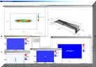
TapeLab is a numerical simulation of the head/tape interface that was specifically designed for use in longitudinal tape recorder configurations. The simulation combines non-linear equations for compressible air bearing, tape mechanics, and tape contact with the head.

The finite element method is used to solve these coupled non-linear equations. TapeLab predicts head/tape spacing and contact pressure between the head and tape. TapeLab also contains a wear model that allows the prediction of head contour after wear with a specific tape. The head/tape interface can be investigated using different tape thickness specifications.

TapeLab is divided into two versions. TapeLab1 is a one-dimensional program, which calculates spacing, contact pressure, and headwear along the tape length only. Tape width is assumed to be infinite; therefore, effects due to partial slots in the head and the tape edge can not be simulated. In these cases, TapeLab2 is required.


Automatic Mesh Generator
TapeLab Automatic Mesh Generator

Automatic Mesh Generator:
Based on the parameters entered in the preprocessor, TapeLab automatically generates the finite element mesh for the tape, air bearing, and contact models. The mesh is generated in two stages. First, a macroscopic model is assembled for the entire span of tape between tape supports near the head. After the macroscopic model is solved, a microscopic model is constructed to calculate the spacing, contact pressure and wear profiles at the region of the head/tape interface. The boundary conditions for the microscopic model are automatically extracted from the solution to the macroscopic model.

System Specifications:

Data Output:

Data output is provided through presentation quality plots and text files for the following parameters:
    Head/tape spacing
    Head/tape contact pressure
    Head/tape air pressure
    Head wear

Hardware:
TapeLab1 runs under the Microsoft Windows operating system on PC compatible personal computers.

Data Input:
Data is input into TapeLab1 using an input file with a number of parameters and a head description. TapeLab1 contains an integral input file editor to speed up file processing and analysis.

Head Geometry

  1. Flat Sections
  2. Cylindrical Sections
  3. Final Head Contouring by Numerical Simulation of Tape Lapping

Alternatively, the head can be specified by a user supplied file of nodal values which indicate head protrusion.

Tape Parameters

  1. Tape Thickness
  2. Tape Density
  3. Effective Young's Modulus in Bending
  4. Poison's Ratio
  5. Tape Surface Roughness: (The tape surface roughness parameters can be measured by MicroPhysics using the Tape Spacing Analyzer)
  6. Tape Tension

Solver:
The equations are solved using the finite element method.

Dynamics:
Tape momentum is included in the calculations. The equations used are steady-state, i.e., tape transient motion is not modeled.

Air Pressure:
Air bearing pressure is modeled using the compressible Reynolds equation with corrected first order slip flow.

Tape Mechanics:
The tape is modeled using plate/shell theory with in-plane deformations and anisotropic tape properties.

Head Wear:
Head wear is calculated in proportion to the predicted head/tape contact pressure. Different areas on the head can be assigned different wear coefficients to simulate differential wear on the head.


Specifications subject to change without notice or obligation.
Copyright © 1999-2020 MicroPhysics, Inc. All Rights Reserved.


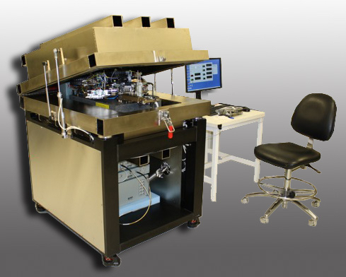
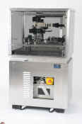
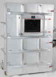
Guzik Spinstand Helium/Altitude Chamber

wpe9.jpg (20763 bytes)


Flying Height 
Tester

wpe9.jpg (20763 bytes)


Altitude Simulation Chamber


Dynamic Protrusion Tester

DHT-Teramar_2.jpg (84373 bytes)


Tape Head Tester

ETT_Photo.jpg (10222 bytes)


Tape Spacing Analyzer

tsa_1.jpg (178895 bytes)


SliderLab

sLab_h1.gif (15091 bytes)


TapeLabH

TapeLabeH.jpg (32695 bytes)


TapeLab

tapeLab2.gif (8351 bytes)